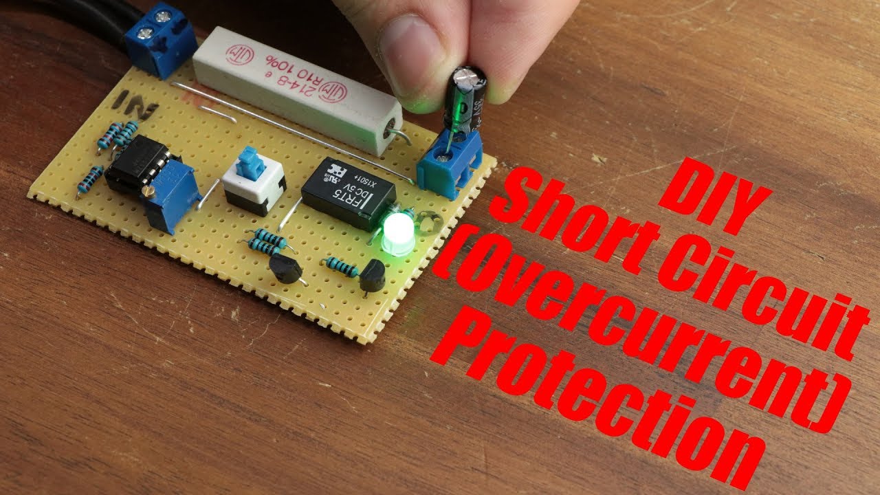
DIY Short Circuit (Overcurrent) Protection
video description
I then thought well I'll study the circuit GreatScott used (photos of the soldering, schematic and components layout ) were very helpful in this as I used mainly the actual soldering and components layout to build the circuit, however, having spent the last 2 days studying both layout photos to build the circuit I finally built it, checked and rechecked that all connections were where they were supposed to be, and finally decided to fire up the masterpiece and marvel at how great it would be to finally have a working short circuit and over current protection for my many Electronic circuits I have built.
Unfortunately though my excitement was soon to be scuppered as this circuit failed at everything, short circuit protection constantly switches the relay on and off (great if you like crickets) utterly useless for everything else, then you have the over current protection section that fails miserably at everything, the circuit I soldered together looks like the circuit in this video as its pretty much a carbon copy as the soldering I did was matched with both the soldered version and parts layouts for reference. From what my limited Electronics experience has concluded is the LM358P in differential mode isn't comparing the 2 voltages correctly, the voltage adjust connected to pin 6 works, Pins 2 and 3 appear to have the correct voltages as one voltage is slightly higher than the other, however, the amplifier section seems to faulter at amplifying the difference between these 2 voltages.
I won't quit and consign this circuit to the bin just yet though, I may put this on the breadboard and have a little experimentation with the circuit who knows I may even learn something, it really would be a shame to throw this circuit in the trash as the layout is nice the soldering is exceptional, it's a very clean circuit with no wires on the soldered side, perfection, such a shame it doesn't work.
I have seen another circuit on YT that's pretty similar to this so may in time build that one and see if that circuit fares any better compared to this one.
Anyway, maybe GreatScott could clarify a few things, Voltage used, I have scrutinised your Instructables on this too.
GreatScott if you read this, I'm not the only person to have built this circuit with no luck, I know I followed the schematic to a tee the 1st time I built this with no errors on the main board, and the 2nd build was a slow and without any errors so I know that I built it according to your working circuit. Maybe you could revisit this circuit and help us out.
Carl
Date: 2020-09-05
Related videos

• TED-Ed





Comments and reviews: 8
Dirk
Tnx Scott, for this circuit. But i have a question. I am building a powersupply and i will put a short circuit in my project. With some research some guys put there short circuit before there voltage regulation. This is a circuit limited to 12v. But what to do if youre powersupply is 24v input? What is best a short circuit before or after youre voltage regulation?
Greetz Preppie_be
reply
Tnx Scott, for this circuit. But i have a question. I am building a powersupply and i will put a short circuit in my project. With some research some guys put there short circuit before there voltage regulation. This is a circuit limited to 12v. But what to do if youre powersupply is 24v input? What is best a short circuit before or after youre voltage regulation?
Greetz Preppie_be
reply
Bad
Yes, I most certainly enjoyed the video. A year from now I'll be able to design my own circuits thanks to your instruction. I'll just toss in a comparator over here to turn that off; . right off the top of my head.
Thanks, I watch your videos almost daily.
reply
Yes, I most certainly enjoyed the video. A year from now I'll be able to design my own circuits thanks to your instruction. I'll just toss in a comparator over here to turn that off; . right off the top of my head.
Thanks, I watch your videos almost daily.
reply
Hung
Hello! I really like this project of yours, I also follow the instructions, Vcc 12v. For some reason it did not work as expected, when I powered the relay on automatically, when the two electrodes touched it did not close the relay. thank you
reply
Hello! I really like this project of yours, I also follow the instructions, Vcc 12v. For some reason it did not work as expected, when I powered the relay on automatically, when the two electrodes touched it did not close the relay. thank you
reply
Divya
There is a problem of short circuit protection in a bms system (cf-4s-30a) due to which the output current (1-2amp) appears only for a few seconds. Why so?
, nd even the output current rating is of 30amp so bms must provide atleast 10a!
reply
There is a problem of short circuit protection in a bms system (cf-4s-30a) due to which the output current (1-2amp) appears only for a few seconds. Why so?
, nd even the output current rating is of 30amp so bms must provide atleast 10a!
reply
education
Please make a video for OverLoad Protection System. LightWeight like this. which will prevent from connecting unwantel load to this circuit by turning off the system for 5 -10 seconds or minutes.
Please Please Please.
reply
Please make a video for OverLoad Protection System. LightWeight like this. which will prevent from connecting unwantel load to this circuit by turning off the system for 5 -10 seconds or minutes.
Please Please Please.
reply
thghho
Hello,
Can you guide me for limiting the output current to 350mA of a power supply (with output 250vdc, max output 15Amp. Should I simply add 0. 22 Ohm 10W (9 Resisters) in Parallel before load?
reply
Hello,
Can you guide me for limiting the output current to 350mA of a power supply (with output 250vdc, max output 15Amp. Should I simply add 0. 22 Ohm 10W (9 Resisters) in Parallel before load?
reply
Nihaludeen
The explaining and concept was really superb. But I have a small doubt at 5. 00 min at default the push button will not be pushed then how the base of the transistor will get pulled to supply.
reply
The explaining and concept was really superb. But I have a small doubt at 5. 00 min at default the push button will not be pushed then how the base of the transistor will get pulled to supply.
reply
Yas
Please can u make simple transformer rise Amper from (1 to 40 A)? To simulation this circt with diferents load! Thanx bro.
reply
Please can u make simple transformer rise Amper from (1 to 40 A)? To simulation this circt with diferents load! Thanx bro.
reply
Add a review, comment
Other channel videos