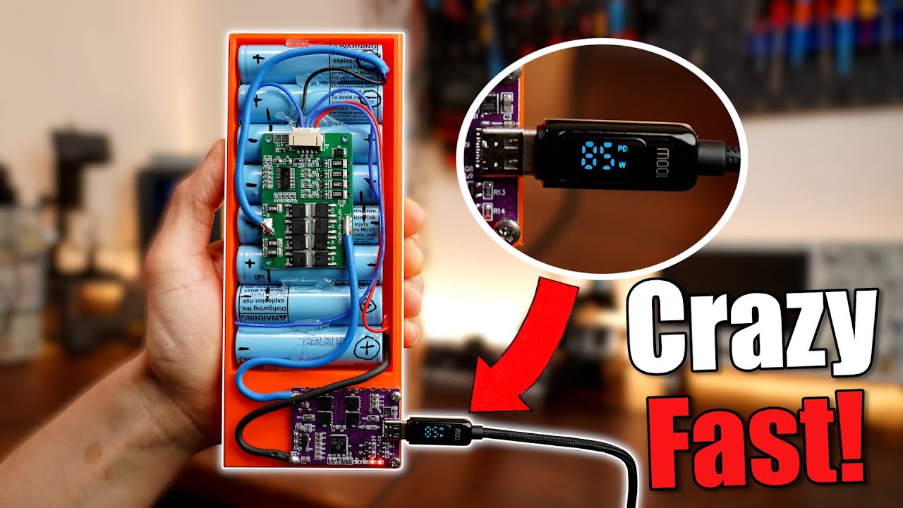
The Fastest Power Bank is Easy to Make with this PCB! (DIY or Buy)
video description
Date: 2022-11-13
Related videos





Comments and reviews: 14
Jovaras
have looked at this exact pcb before as well as the manufacturer. Their stuff seems quality. The product which caught my eye the most was the DIY powerbank from them themselves, where you just add your own batteries. There are different models with different amount of battery holders for example 8, 16 and 24 cells. It uses the same chip IP5389 and in my opinion is the best case scenario because you get both high capacity and easy of use.
reply
have looked at this exact pcb before as well as the manufacturer. Their stuff seems quality. The product which caught my eye the most was the DIY powerbank from them themselves, where you just add your own batteries. There are different models with different amount of battery holders for example 8, 16 and 24 cells. It uses the same chip IP5389 and in my opinion is the best case scenario because you get both high capacity and easy of use.
reply
Daniel
What battery spot welder is that? I actually built my own battery spot welder awhile back using a car battery, an old car starter solenoid, an Arduino board, a button, and a relay. I didn't have the proper spot welder probes either so I used some wire and a couple nails. It had no way to set the output power, but I could set the firing pulse length to get a hotter or colder weld. It worked great though!
reply
What battery spot welder is that? I actually built my own battery spot welder awhile back using a car battery, an old car starter solenoid, an Arduino board, a button, and a relay. I didn't have the proper spot welder probes either so I used some wire and a couple nails. It had no way to set the output power, but I could set the firing pulse length to get a hotter or colder weld. It worked great though!
reply
Pixel
do i understand it correctly that the fuel gauge thing is only relevant for the LED indicators?
all the over voltage and under voltage stuff is happening independently of that right?
That would mean i can buy two of these boards and connect them to the same battery pack so i could charge and discharge at the same time or have two port that can provide power at the same time.
reply
do i understand it correctly that the fuel gauge thing is only relevant for the LED indicators?
all the over voltage and under voltage stuff is happening independently of that right?
That would mean i can buy two of these boards and connect them to the same battery pack so i could charge and discharge at the same time or have two port that can provide power at the same time.
reply
Wizzard
The measuring the capacity of the battery (the 4 leds) was interesting for me.
1 idea: Many things (phone and much more) work with 1 lipocell. What if you have only a external battery to use this things? You can use a much bigger battery, your phone cannot fall to the ground, old devices can work for ever, it is easy to change the battery and thiefs get a problem: )
reply
The measuring the capacity of the battery (the 4 leds) was interesting for me.
1 idea: Many things (phone and much more) work with 1 lipocell. What if you have only a external battery to use this things? You can use a much bigger battery, your phone cannot fall to the ground, old devices can work for ever, it is easy to change the battery and thiefs get a problem: )
reply
Matthew
I love your videos. You're so smart and informative. Thank you for always putting it great content. Could you add more batteries to the buy version so you'd get the best of both worlds? Since you can 3D print another case it wouldn't be a challenge for the extra batteries. Or does the PCB only allow a maximum wH?
reply
I love your videos. You're so smart and informative. Thank you for always putting it great content. Could you add more batteries to the buy version so you'd get the best of both worlds? Since you can 3D print another case it wouldn't be a challenge for the extra batteries. Or does the PCB only allow a maximum wH?
reply
Demi
You going through the datasheet really brightened up things for me about these boards. Those definitely will be better for projects with higher cell count 4+ and safer than usual charging power adapters. Might add one of those to my speaker to finally have a reliable way of charging the 5s battery inside it.
reply
You going through the datasheet really brightened up things for me about these boards. Those definitely will be better for projects with higher cell count 4+ and safer than usual charging power adapters. Might add one of those to my speaker to finally have a reliable way of charging the 5s battery inside it.
reply
CAMB
The purple PCB says that the R5 resistor can be set depending on the cell capacity. To be more specific 6. 2k Ohm pr 5Ah. But does that mean if i have a 120 Ah battery, that i can just set it to 148. 8kOhm? Their table doesnt show anything past 25Ah.
Does anyone know or have experimented with this?
reply
The purple PCB says that the R5 resistor can be set depending on the cell capacity. To be more specific 6. 2k Ohm pr 5Ah. But does that mean if i have a 120 Ah battery, that i can just set it to 148. 8kOhm? Their table doesnt show anything past 25Ah.
Does anyone know or have experimented with this?
reply
Pere
i wanted to make some battery pack that is able to charge my laptop, i looked around and had some ideas the best one was to make usb c power bank with ability to charge at least 20V 3A and there was adapters for laptop barrel input to use usb c. Only thing i needed was some board like this, thank you
reply
i wanted to make some battery pack that is able to charge my laptop, i looked around and had some ideas the best one was to make usb c power bank with ability to charge at least 20V 3A and there was adapters for laptop barrel input to use usb c. Only thing i needed was some board like this, thank you
reply
Daniel
Thanks for highlighting this product! I've been looking for something like this for an off-grid wind turbine, so I wonder if the circuit board will work if I bypass the BMS.
You absolutely love the sentence structure not only X, but also Y XD I challenge you to make a video without it!
reply
Thanks for highlighting this product! I've been looking for something like this for an off-grid wind turbine, so I wonder if the circuit board will work if I bypass the BMS.
You absolutely love the sentence structure not only X, but also Y XD I challenge you to make a video without it!
reply
Sysshad
That's crazy! Not even hot, must be some crazy low rds-on ohms on those mosfets.
And that the usb can handle that much with its small connectors is also insane: D
What module did you use to simulate the different charging standards? I see it quickly being shown in the video.
reply
That's crazy! Not even hot, must be some crazy low rds-on ohms on those mosfets.
And that the usb can handle that much with its small connectors is also insane: D
What module did you use to simulate the different charging standards? I see it quickly being shown in the video.
reply
akh345
Thank you for this very insightful video! I wonder whether exposing lithium ion cells to high-temp soldering at 9: 44 and to hot glue at 8: 49 will degrade their performance. Isn't that why we use spot welding on nickel strips rather than soldering in the first place?
reply
Thank you for this very insightful video! I wonder whether exposing lithium ion cells to high-temp soldering at 9: 44 and to hot glue at 8: 49 will degrade their performance. Isn't that why we use spot welding on nickel strips rather than soldering in the first place?
reply
Nick
I've been trying to find a solution for my Pi 4 mini server, something that works as a battery backup but also as a UPS. Post off the shelf options cause a voltage drop when it's plugged in or unplugged for charging, causing the Pi to restart. Maybe it's time for DIY.
reply
I've been trying to find a solution for my Pi 4 mini server, something that works as a battery backup but also as a UPS. Post off the shelf options cause a voltage drop when it's plugged in or unplugged for charging, causing the Pi to restart. Maybe it's time for DIY.
reply
emre
According to the efficiency graph at 8: 23 I couldn't understand how board kept cool at 90w output. Looks like efficiency is about 90 percent which means around 9w of energy should be dissipated as heat. How can be the temperature of the board is 45 degree celcius?
reply
According to the efficiency graph at 8: 23 I couldn't understand how board kept cool at 90w output. Looks like efficiency is about 90 percent which means around 9w of energy should be dissipated as heat. How can be the temperature of the board is 45 degree celcius?
reply
Uzi
Not too long ago I've made my own modular powerbank using laptop batteries. With swappable batteries, and a buck boost converter it provides great results to a USB 3. 1. I think I'll revisit it to give me USB C and some power monitoring.
Great Video (:
reply
Not too long ago I've made my own modular powerbank using laptop batteries. With swappable batteries, and a buck boost converter it provides great results to a USB 3. 1. I think I'll revisit it to give me USB C and some power monitoring.
Great Video (:
reply
Add a review, comment
Other channel videos