
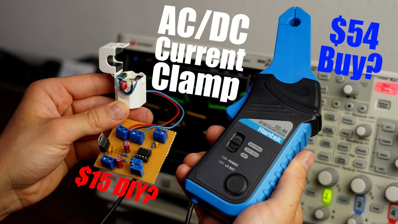
Can my 15 DIY AC/DC Current Clamp keep up with a commercial one? DIY or Buy
video description
Date: 2021-07-04
Related videos





Comments and reviews: 10
Mark
Hmm, okay, 5kHz is no way good enough for investigating switch mode power supply operation. The other problem with current sense resistors is that they have inductance. A more accurate equation for voltage across a sense resistor is V = iR + Ldi/dt, and if the current is changing fast, the voltage signal is useless for observing the current waveform.
The hardest part of measuring current accurately is accounting for the change in core characteristics with a gapped core. Rather than break the flux path, it is better to break the current path. Less convenient to be sure, but far more accurate and cheaper than a high quality high bandwidth current probe.
The solution I use is an LEM current transducer, with a split supply from a dc-dc converter, all powered from a 12V plug top adapter. I mounted this all in a box with a 2. 1mm dc power connector and a BNC for the signal output. Yes I have to break the current path, pass the wire through the sensor and reconnect it, but I get a superb signal with a bandwidth of up to 200kHz with the LA 55-P transducer, with an output resistance calibrated for 10mV per amp. It works REALLY well!
reply
Hmm, okay, 5kHz is no way good enough for investigating switch mode power supply operation. The other problem with current sense resistors is that they have inductance. A more accurate equation for voltage across a sense resistor is V = iR + Ldi/dt, and if the current is changing fast, the voltage signal is useless for observing the current waveform.
The hardest part of measuring current accurately is accounting for the change in core characteristics with a gapped core. Rather than break the flux path, it is better to break the current path. Less convenient to be sure, but far more accurate and cheaper than a high quality high bandwidth current probe.
The solution I use is an LEM current transducer, with a split supply from a dc-dc converter, all powered from a 12V plug top adapter. I mounted this all in a box with a 2. 1mm dc power connector and a BNC for the signal output. Yes I have to break the current path, pass the wire through the sensor and reconnect it, but I get a superb signal with a bandwidth of up to 200kHz with the LA 55-P transducer, with an output resistance calibrated for 10mV per amp. It works REALLY well!
reply
panssari
can u make buck-boost converter whit arduino nano, current limit(not like it cut supply, but doesnt let over current run) and like tree to four output. or just blueprints where u make easily understandable ciruit blueprint. I have done tried copy blueprints from ur videos but its hard when try use op amps. sometimes blueprint doesnt show all connections like vcc, ground, and orhers. Yah I know u maybe dont need them but it would bee easier if u show that u dont have to connect them also please put tags to only vcc, and ground. its pretty hard to understand adding current limit fea. video ciruit because there is ICIP connection connected nowere.
Thanks for video. these videos are gold for me: . Now u have to show how to mane oscilloscope because whitout it i cant use this clamp. are those electric component from europe? because in finland we have to pay 24% Tax if we buy outside from europe. Pleace make more of these type projects(sheap and good)
and here is more questions: do u have recomedions for good circuit simulator whit arduino, coils, other components?
reply
can u make buck-boost converter whit arduino nano, current limit(not like it cut supply, but doesnt let over current run) and like tree to four output. or just blueprints where u make easily understandable ciruit blueprint. I have done tried copy blueprints from ur videos but its hard when try use op amps. sometimes blueprint doesnt show all connections like vcc, ground, and orhers. Yah I know u maybe dont need them but it would bee easier if u show that u dont have to connect them also please put tags to only vcc, and ground. its pretty hard to understand adding current limit fea. video ciruit because there is ICIP connection connected nowere.
Thanks for video. these videos are gold for me: . Now u have to show how to mane oscilloscope because whitout it i cant use this clamp. are those electric component from europe? because in finland we have to pay 24% Tax if we buy outside from europe. Pleace make more of these type projects(sheap and good)
and here is more questions: do u have recomedions for good circuit simulator whit arduino, coils, other components?
reply
Piotr
Great Scott, that's a decent circuit. To make it work on higher frequences, solder couple wires more to the spare opamp you have already there! Use it as a buffer, because in current setup you might have create some filter between virtual ground and coax. In my opinion, if its working great at low frequencies, this would be the reason.
BTW I have looked for a while for nice inexpensive current clamp and for sure going to build that.
Another option for even cheaper way of measuring the current would be to use small value resistor (0, 1 ohm for example) and amplify the output with opamps to suitable level. Good for electronics and more accurate. Regards.
reply
Great Scott, that's a decent circuit. To make it work on higher frequences, solder couple wires more to the spare opamp you have already there! Use it as a buffer, because in current setup you might have create some filter between virtual ground and coax. In my opinion, if its working great at low frequencies, this would be the reason.
BTW I have looked for a while for nice inexpensive current clamp and for sure going to build that.
Another option for even cheaper way of measuring the current would be to use small value resistor (0, 1 ohm for example) and amplify the output with opamps to suitable level. Good for electronics and more accurate. Regards.
reply
The
I'd posit two areas for investigation
1. the voltage rail splitting. As you mentioned, resistor-capacitor network is ugly. I don't know how well it copes with higher frequency demands. I've seen rail splitting ICs for DIY audio devices, which have a couple of op-amps packaged in them.
2. The OpAmp's frequency response curves. The output curves really look like they're being filtered.
2. 1 oooooh, the perfboards' traces leading to stray capacitance and other unwanted features.
It's highly likely that a designed PCB could bring this excellent proof of concept up to being very functional.
Nice work!
reply
I'd posit two areas for investigation
1. the voltage rail splitting. As you mentioned, resistor-capacitor network is ugly. I don't know how well it copes with higher frequency demands. I've seen rail splitting ICs for DIY audio devices, which have a couple of op-amps packaged in them.
2. The OpAmp's frequency response curves. The output curves really look like they're being filtered.
2. 1 oooooh, the perfboards' traces leading to stray capacitance and other unwanted features.
It's highly likely that a designed PCB could bring this excellent proof of concept up to being very functional.
Nice work!
reply
Carsten
Consider buying other solder tips if it takes you one hour for such a small circuit. A small conical tip has a low mass and their for heat capacity and a bad geometry for transfer of heat to the board. I use almost only wedge shaped ones. To reduce thermal stress, I use bigger ones. The higher mass means the solder don't get solid as easy, and I don't have to stay on the point as long or even increase the temperature.
The current clamp is a nice idea. I rarely use one at home so I am used to borrow the one from work when I need it.
reply
Consider buying other solder tips if it takes you one hour for such a small circuit. A small conical tip has a low mass and their for heat capacity and a bad geometry for transfer of heat to the board. I use almost only wedge shaped ones. To reduce thermal stress, I use bigger ones. The higher mass means the solder don't get solid as easy, and I don't have to stay on the point as long or even increase the temperature.
The current clamp is a nice idea. I rarely use one at home so I am used to borrow the one from work when I need it.
reply
Todd
Just a guess w/o calculations: At high frequency, the conductance of the capacitors in the voltage divider probe come into play. At high frequency these become short circuits. probably with different conductance thus throwing off your offset. But worse, they short out the voltage coming from the Hall effect transducer. In an AC mode, using inductors instead of capacitors causes them to have the opposite effect. But before trying that I would experiment first with eliminating the capacitors in the AC case.
reply
Just a guess w/o calculations: At high frequency, the conductance of the capacitors in the voltage divider probe come into play. At high frequency these become short circuits. probably with different conductance thus throwing off your offset. But worse, they short out the voltage coming from the Hall effect transducer. In an AC mode, using inductors instead of capacitors causes them to have the opposite effect. But before trying that I would experiment first with eliminating the capacitors in the AC case.
reply
Pedro
You need to be mindful of your amplifier's bandwidth. Depending on your opamp IC, there is a limit on the maximum frequency it can operate at. And also, for such small internal voltages, some EMI shielding and signal traces isolation might be desirable. Furthermore, as MikrySoft has already said, there is another current clamp design, which uses an active secondary coil. The purpose of this coil is to induce an oposing flux such that the total magnetic flux being measured by the Hall-effect sensor is 0.
reply
You need to be mindful of your amplifier's bandwidth. Depending on your opamp IC, there is a limit on the maximum frequency it can operate at. And also, for such small internal voltages, some EMI shielding and signal traces isolation might be desirable. Furthermore, as MikrySoft has already said, there is another current clamp design, which uses an active secondary coil. The purpose of this coil is to induce an oposing flux such that the total magnetic flux being measured by the Hall-effect sensor is 0.
reply
Severin
Great Video thanks!
One comment to the bad AC performance. If I saw it correctly you almost had a Gain of 200 if the 1A current ceated as shown a voltage of 500uV this would decrease your Opamp Bandwith from 4Mhz to 20kHz. (GBP 4MHz Typical) which would decrease the Amplitude of the Harmoics incredible creating potential the bad shapes. Possible solution at least to try it different Opamp with higher bandwidth. May take a look at the one used in the commercial clamp. What do you think?
reply
Great Video thanks!
One comment to the bad AC performance. If I saw it correctly you almost had a Gain of 200 if the 1A current ceated as shown a voltage of 500uV this would decrease your Opamp Bandwith from 4Mhz to 20kHz. (GBP 4MHz Typical) which would decrease the Amplitude of the Harmoics incredible creating potential the bad shapes. Possible solution at least to try it different Opamp with higher bandwidth. May take a look at the one used in the commercial clamp. What do you think?
reply
jafinch78
Thanks for sharing! Literally just commented regarding a few days back on Kerry Wong's latest video where I'll be needing for the hybrid CVT MG's design inspection and performance characterization. Now am even more-so planning to make and appreciate the insight. Wondering if those plates are Metglas, Permalloy, MuMetal or what? Was thinking about just using a cheapo current clamp meter hacked out and I think you went even more cost effectively. Really awesome to watch as always!
reply
Thanks for sharing! Literally just commented regarding a few days back on Kerry Wong's latest video where I'll be needing for the hybrid CVT MG's design inspection and performance characterization. Now am even more-so planning to make and appreciate the insight. Wondering if those plates are Metglas, Permalloy, MuMetal or what? Was thinking about just using a cheapo current clamp meter hacked out and I think you went even more cost effectively. Really awesome to watch as always!
reply
Tech
Just some tips for you. I checked your design and then i went through the datasheet of the parts and i noticed some issues. Now you have connected a 100nf capacitor across the power pins of the hall effect sensor. Just try to put a 100pf cap across that and try it again. I dont have an exact logic of how and why it will work but its just an idea or just a hunch which i had after reading the datasheet. It might solve your high frequency reading issues
reply
Just some tips for you. I checked your design and then i went through the datasheet of the parts and i noticed some issues. Now you have connected a 100nf capacitor across the power pins of the hall effect sensor. Just try to put a 100pf cap across that and try it again. I dont have an exact logic of how and why it will work but its just an idea or just a hunch which i had after reading the datasheet. It might solve your high frequency reading issues
reply
Add a review, comment
Other channel videos
 13:25
13:25 13:52
13:52


 11:24
11:24