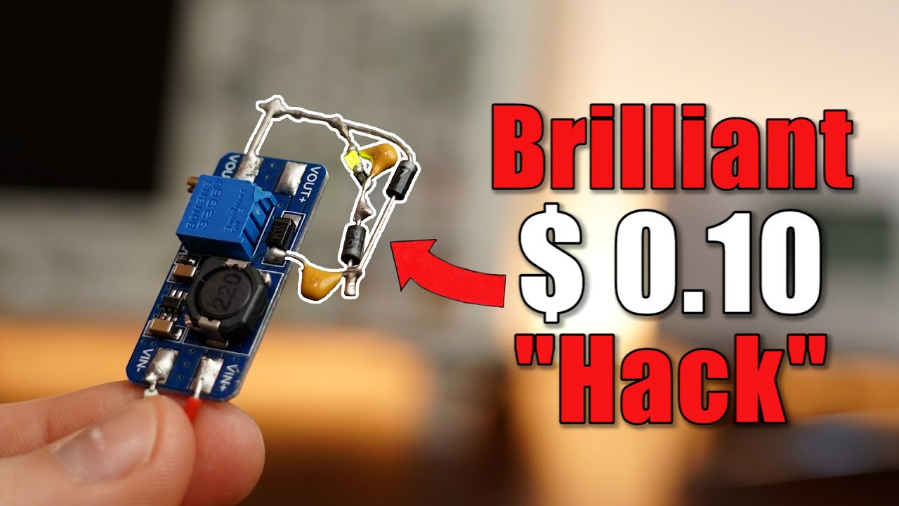
Negative Voltages are more important than you think! So here is how to make them!
video description
Date: 2022-04-17
Related videos





Comments and reviews: 9
JeSmart
Such a good video that I needed some weeks ago when i designed a positive and negative voltage and now I have more info thanks.
Another way is to use a Buck converter, if you see the schematics of a inverter converter and a buck convertee you will see the same image just flip so the lm2596 can generate negative voltage if you put GNd to output and Voltage to. input, it bootstrap the voltage so if you get -12V from 5V the input will see 17V that is the disavantage the limit would be the max input voltage of the IC but it is pretty straight forward to get negative voltage like that without soldering anything
reply
Such a good video that I needed some weeks ago when i designed a positive and negative voltage and now I have more info thanks.
Another way is to use a Buck converter, if you see the schematics of a inverter converter and a buck convertee you will see the same image just flip so the lm2596 can generate negative voltage if you put GNd to output and Voltage to. input, it bootstrap the voltage so if you get -12V from 5V the input will see 17V that is the disavantage the limit would be the max input voltage of the IC but it is pretty straight forward to get negative voltage like that without soldering anything
reply
Gijs
When joining 2 secondary coils of the same transformer, one must double check the correct sides are connected, or else you will end up with 2 separate positive outputs and a common ground.
Further on combining coils of transformers.
When combining 2 outputs of a transformer on both ends to increase the amount of current, you must do that after the bridge rectifier you should use for each. Learned that the hard way; )
reply
When joining 2 secondary coils of the same transformer, one must double check the correct sides are connected, or else you will end up with 2 separate positive outputs and a common ground.
Further on combining coils of transformers.
When combining 2 outputs of a transformer on both ends to increase the amount of current, you must do that after the bridge rectifier you should use for each. Learned that the hard way; )
reply
MCMH2000
This simple charge pump circuit I used when I wanted to get an old scrap LCD matrix display from an old phone to work.
With a polish datasheet and too much free time I was able to make a library for it, to use it with an Arduino.
Only thing left was the negative voltage. So I googled and found this charge pump design which I put together with scrap parts from old circuitbords and it worked: D
reply
This simple charge pump circuit I used when I wanted to get an old scrap LCD matrix display from an old phone to work.
With a polish datasheet and too much free time I was able to make a library for it, to use it with an Arduino.
Only thing left was the negative voltage. So I googled and found this charge pump design which I put together with scrap parts from old circuitbords and it worked: D
reply
TheBunnyChower
Dear GreatScott,
Thank you for making this informative video on how to generate negative voltages, it's very useful.
However, I'd like to ask that you do not use my search history again as an idea for another video next time: it's a deep, dark rabbit hole and it's not advisable you tread further into it.
Warm Regards,
A random fan.
reply
Dear GreatScott,
Thank you for making this informative video on how to generate negative voltages, it's very useful.
However, I'd like to ask that you do not use my search history again as an idea for another video next time: it's a deep, dark rabbit hole and it's not advisable you tread further into it.
Warm Regards,
A random fan.
reply
MorRobots
The moment you said Check out the links in the description and I saw that manila background and the dual 2N3904 with the two 1N4148 forming the voltage divider I was like. Yep, read that page already! That's a great reference for creating virtual grounds using essentially linear components and no switching or charge pumps.
reply
The moment you said Check out the links in the description and I saw that manila background and the dual 2N3904 with the two 1N4148 forming the voltage divider I was like. Yep, read that page already! That's a great reference for creating virtual grounds using essentially linear components and no switching or charge pumps.
reply
Peter
Most switching power adapters are isolated in reference to AC power ground, and we can cascade such outputs and achieve positive/negative power rail. If you want a micro volt potential difference between the center ground of your DC power supply and the earth ground, connect them with a 1 M-ohm resistor.
reply
Most switching power adapters are isolated in reference to AC power ground, and we can cascade such outputs and achieve positive/negative power rail. If you want a micro volt potential difference between the center ground of your DC power supply and the earth ground, connect them with a 1 M-ohm resistor.
reply
Mad
important to note that the opamp in the last solution solves the problem of imbalance for small currents. Just to be on the safe side it is really useful to use a push-pull current amplifier configuration so the opamp doesnt get so stressed and the ground is more stable for a wider range of currents: )
reply
important to note that the opamp in the last solution solves the problem of imbalance for small currents. Just to be on the safe side it is really useful to use a push-pull current amplifier configuration so the opamp doesnt get so stressed and the ground is more stable for a wider range of currents: )
reply
Nyein
Can I request a control circuit that can switch direct dc coming from battery and dc output power supply to a 3d printer. it will work like a ups except it only switch between battery power and power supply dc output to a 3d printer. I think you'll get it. Thank you so much.
reply
Can I request a control circuit that can switch direct dc coming from battery and dc output power supply to a 3d printer. it will work like a ups except it only switch between battery power and power supply dc output to a 3d printer. I think you'll get it. Thank you so much.
reply
Byron
Use two AC power to DC smps and connect their outputs - to +. (Don't use wall warts since they are often not isolated) Meanwell makes modules for a few bucks. Reduce switching noise with ferrite beads and cap filters and/or linear regulators.
reply
Use two AC power to DC smps and connect their outputs - to +. (Don't use wall warts since they are often not isolated) Meanwell makes modules for a few bucks. Reduce switching noise with ferrite beads and cap filters and/or linear regulators.
reply
Add a review, comment
Other channel videos