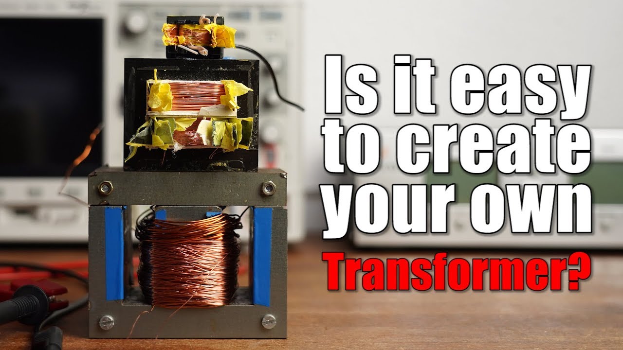
Is it easy to create your own Transformer? Everything you need to know about Transformers! EB#42
video description
Date: 2020-09-05
Related videos




Comments and reviews: 9
Pablo
This video is so awesome.
At my work we built a couple of Three-Phase transformers that were designed to transform 110VAC to 50VAC at 125Hz. We were struggling with saturation and we had to adjust the design of our system, thus increasing the operating frequency from 125Hz to 250Hz (not such a big deal since we were going to use a three-phase rectifier for those phase-phase voltages)
This video was very educative.
Can you please make a video explaining Generators or Alternators? That would be so awesome
reply
This video is so awesome.
At my work we built a couple of Three-Phase transformers that were designed to transform 110VAC to 50VAC at 125Hz. We were struggling with saturation and we had to adjust the design of our system, thus increasing the operating frequency from 125Hz to 250Hz (not such a big deal since we were going to use a three-phase rectifier for those phase-phase voltages)
This video was very educative.
Can you please make a video explaining Generators or Alternators? That would be so awesome
reply
Jorge
I'm confused by the explanation of why the current through the primary winding is less then V/Z. Because the back EMF induced by the current in an inductor is nothing else than the phenomenon responsible for the reactive part of its impedance in the first place. And a transformer with the secondary winding open is just an inductor. So, there must be something else that is causing that discrepancy. Maybe the inductance measurement was inaccurate, or done at a frequency other than 50Hz.
reply
I'm confused by the explanation of why the current through the primary winding is less then V/Z. Because the back EMF induced by the current in an inductor is nothing else than the phenomenon responsible for the reactive part of its impedance in the first place. And a transformer with the secondary winding open is just an inductor. So, there must be something else that is causing that discrepancy. Maybe the inductance measurement was inaccurate, or done at a frequency other than 50Hz.
reply
Steve
I bought a transformer with 2 x 24v secondary outputs and put a bridge rectifier on each output. Without load each output was measuring 49vdc? Shouldn't this be closer to the rated 24v power of each secondary output? Or is this simply a no load voltage. I did not put either output under load until I could get a better understanding of the dual output transformers. The bridge rectifiers used were package type and not made fr inn 4 separate diodes.
reply
I bought a transformer with 2 x 24v secondary outputs and put a bridge rectifier on each output. Without load each output was measuring 49vdc? Shouldn't this be closer to the rated 24v power of each secondary output? Or is this simply a no load voltage. I did not put either output under load until I could get a better understanding of the dual output transformers. The bridge rectifiers used were package type and not made fr inn 4 separate diodes.
reply
Spatial
I have the same USB charger you showed at video start, but it was sold in switzerland with a different package!
But the PCB is still the same! Galvanical isolation of this transformer is very bad so you should protect yourself by connecting the negative output of the phone charger to the ground of a mains voltage plug!
reply
I have the same USB charger you showed at video start, but it was sold in switzerland with a different package!
But the PCB is still the same! Galvanical isolation of this transformer is very bad so you should protect yourself by connecting the negative output of the phone charger to the ground of a mains voltage plug!
reply
Aldrin
Great scott sir, please make a video describing about AC to DC smps. i. e. Str w6754 ic based smps. And also include about err amp, feed back system. Please I request you, I am very curious to know about this topic from you, since your videos have been very much attracting me from the last 3 years.
reply
Great scott sir, please make a video describing about AC to DC smps. i. e. Str w6754 ic based smps. And also include about err amp, feed back system. Please I request you, I am very curious to know about this topic from you, since your videos have been very much attracting me from the last 3 years.
reply
Research
I used to make my own transformers baxk about 20 years ago, they worked well. Mine were designed for 25khz and up tho for switching power suppliy use. Calculated about 88% efficiency average on my diy transformers. Used to take the core out of commercial ones and rewind it for what i needed
reply
I used to make my own transformers baxk about 20 years ago, they worked well. Mine were designed for 25khz and up tho for switching power suppliy use. Calculated about 88% efficiency average on my diy transformers. Used to take the core out of commercial ones and rewind it for what i needed
reply
Jonas
Hi Greatscott.
I'm creating a diy spot-welder with a MOT and a timer/control board. In the primary coil there is a capacitor in series on the input of the primary coil.
Why/what does it do?
Does it need to be there? (It broke when removing the secondary coil)
Thanks
reply
Hi Greatscott.
I'm creating a diy spot-welder with a MOT and a timer/control board. In the primary coil there is a capacitor in series on the input of the primary coil.
Why/what does it do?
Does it need to be there? (It broke when removing the secondary coil)
Thanks
reply
Steam
I love your video so. much, but i want you to help me with this. i am working on ultra low voltage boost converter to light a LED by using Thermal Electric Generator but i dont know what to do please helpppp me =(
reply
I love your video so. much, but i want you to help me with this. i am working on ultra low voltage boost converter to light a LED by using Thermal Electric Generator but i dont know what to do please helpppp me =(
reply
Carlos
I've been trying to understand this in highschool but my teacher, men! I wished see this video 10 years ago
P. s. I speak Spanish so can you add subtitles in other languages this is very important knowledge
reply
I've been trying to understand this in highschool but my teacher, men! I wished see this video 10 years ago
P. s. I speak Spanish so can you add subtitles in other languages this is very important knowledge
reply
Add a review, comment
Other channel videos


 11:12
11:12